Hack UR Baubles: Assembly Instructions
A project by Michael Grant & Megan Smith. hack ur baubles will be available in December 2013.
Customize your Christmas lights and add a personal narrative to your baubles with light and sound sensors. Build your Christmas experience to your taste and then control your project with a TV remote. Beam out morse message lights or become a human blinking and singing Christmas tree!

Board will be available for purchase in a DIY kit or stand alone on this Tindie page.
There are two variations of the ‘Hack UR Baubles’ project: battery powered & adapter powered.
This schematic shows both variations. The instructions below detail the specific builds.
Click for larger image.

INSTRUCTIONS
When assembling a circuit board, start with the shortest components first.
This way, when the board is turned over to solder, the parts rest on the table and don’t fall out.
1. RESISTORS
| Bend each resistor before inserting them. The resistors are marked with colored bands to indicate value. The value and color code for each resistor is in the chart. | |||||||||||||||||||||||||
| On the bauble board – each resistor is labeled ‘R’ followed by a number. The numbers increment in a clockwise pattern, starting at the top left of the circuit board.
Place all the resistors according to the guide below. Then, carefully flip the board over. |
|||||||||||||||||||||||||
|
|||||||||||||||||||||||||
| Solder each resistor in place and then trim off the extra bits. | |||||||||||||||||||||||||
2. CERAMIC CAPACITORS
| All the ceramic capacitors are 0.1uF except for C4, which is 0.047uF. The capacitor symbol on the circuit board looks like this, with incrementing numbers. |  |
| Place the 0.047uF ceramic capacitor, labeled ‘473’ (which means 47 + 3 zeros pF) in C4. |  |
| Then, place the remaining 10 ceramic capacitors in C1, C2, C3, C5, C6, C8, C9, C11, C12 & C13. The 0.1uF ceramic capacitors are labeled ‘104’ which means 10 + 4 zeros pF. |  |
| Carefully flip the board over. Solder each capacitor in place, and then trim off the extra bits. |
3. IC SOCKET
| The IC sockets make it easy to change the chips, they also protect the chips against heat from soldering. There are two on the circuit board, IC1 and IC2. They look like this. |  |
| The footprint symbol on the circuit board looks like this.
Note – There are two IC sockets at different lengths. The notch on the end keeps pin 1 of the chips aligned. |
 |
| Place each IC socket. Then, carefully flip the board over. Solder each IC socket in place, and then trim off the extra bits. |
4. LIGHT SENSOR
| The light sensor is a light dependent variable resistor. This item has no polarity, ie. it doesn’t matter which pin goes in which hole. It looks like this. | |
| The footprint symbol on the circuit board looks like this. Put it in, flip it over, solder and trim! |  |
5. BUTTON
| The button is a simple 4 legged animal with it’s back to the sun, it snaps in place any which way it fits. Tastes clicky. | 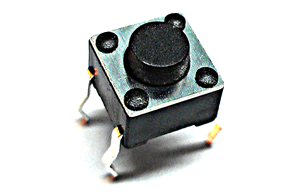 |
| It’s footprint looks like this. It’s up near the top, where the bauble hangs. Place, flip, solder & trim. |  |
6. MICROPHONE
| The microphone is an electret type used to sense sense sound to modulate the LEDs. |  |
| The footprint looks like this, with two offset pins that determine it’s fit. Place, flip, solder, trim. |  |
7. RESONATOR
| The resonator is the clock source for the microcontroller which runs at 16MHz, it looks like this. |  |
| It goes into this footprint any which way it fits. Place, flip, solder, trim.
SPECIAL NOTE: When soldering the resonator, don’t dwell as too much heat can damage it. |
 |
8. TRANSISTORS
| The transistor is a switch. This part is a BC548, a small signal NPN transistor. There are 3 of them in the circuit. |  |
| The shape of the body determines how it fits. Match the round and flat edges to the footprint on the circuit board. Place, flip, solder, trim. |  |
9. SPEAKER
| This is a magnetic speaker which has better frequency response than a piezo speaker. |  |
| It is polarized, the plus size can be seen on the footprint and on the bottom of the speaker as well. Make sure it gets in the right way around. Place, flip, solder, trim. |  |
10. INFRARED LEDs
| There are two infrared LEDs on the circuit board. They are used to communicate with other baubles or with a TV. LEDs are polarized, the long leg is positive. Inside the LED the anvil shape is typically negative. | |
| The footprint looks like this and like the LED, has a flat edge to indicate negative. Place, flip, solder, trim. |  |
11. INFRARED DEMODULATOR
| This is the receiver for infrared remote signals, it contains some demodulation circuitry and a window filter around 38Khz. The part number is VS1838B. | |
| The footprint is designed to accept different models. For this tutorial occupy only the side nearest the label ‘IRX1’, which has the ground pin in the center. Place, flip, solder, trim.
SPECIAL NOTE: When soldering the demodulator, don’t dwell as too much heat can damage it. |
 |
12. POTENTIOMETERS
| There are two potentiometers in the circuit. The first one is to adjust offset for the audio line in signal, it’s the smaller of the two. |  |
| Like most potentiometers, it has three legs and this makes it easy to fit as the footprint illustrates. |  |
| The second potentiometer is bigger. It is used as a general purpose adjustment knob. |  |
| Its footprint is bigger and has a couple of additional solder points for mechanical stability.
Place both potentiometers, flip, solder & trim. |
 |
13. RCA CONNECTOR
| This connector is a used for audio line in, as an alternative to the microphone. |  |
| The footprint is at the edge of the circuit board to facilitate plugging in an audio source such as an MP3 player.
Place, flip, solder, trim. |
 |
14. ELECTROLYTIC CAPACITORS
| There are three capacitors. C7 is smaller and both C10 and C14 are the same size.
Note – The white stripe indicates negative. |
 |
| On the footprint, the white half circle marks the negative terminal. The shorter leg of the capacitor goes in the negative terminal.
Place C7, flip & solder. Place C10 & C14, flip, solder and then trim all three. |
 |
ADDITIONAL INSTRUCTIONS FOR (A)DAPTER POWERED BAUBLE.
A1. DIODE
| This diode is a 1N4007, it protects the regulator against reverse voltage. Observe the polarity. The stripe on the part indicates the negative terminal. | |
| Match the negative side with the stripe on the footprint. Place, flip, solder, trim. |  |
A2. VOLTAGE REGULATOR
| This part is an LM7805 in a TO220 package. The voltage regulator drops the incoming voltage to 5v for the microcontroller. |  |
| The footprint looks like this. The heatsink tab aligns with the stripe on the footprint. It will get warm with normal operation. Place, flip, solder, trim. |  |
A3. BARREL POWER CONNECTOR
| This is a 5.5mm barrel power connector. It is the main power input to run the LED strings. It can be up to 24v DC. |  |
| This is the footprint symbol. It only fits one way with the opening facing off board. Place, flip and use lots of solder. |  |
CONNECTING LEDS TO THE (A)DAPTER POWERED BAUBLE
| The adapter powered bauble switches the LEDs at the adapter voltage, 24 volts DC. White LEDs drop about 3 volts so we can drive 7 LEDs in series. | |
 |
|
| The best source of LEDs for this are LED Christmas light strings. They are already wired in series and we can cut them to sections of seven. The schematic below illustrates how they come wired, parallel sets of series strings. | |
 |
ADDITIONAL INSTRUCTIONS FOR (B)ATTERY POWERED BAUBLE.
B1. SWITCH
| This part is the power switch to the battery. It doesn’t matter which way it fits. |  |
| The footprint is just over the microcontroller and looks like this. Place, flip, solder, trim. |  |
B2. REGULATOR BYPASS
| The Arduino operates directly on battery voltage, so it is necessary to bypass the regulator with a wire joining the two outside pads. Any bit of wire will do just make sure it forms a bridge and doesn’t touch the middle pad which is round. Solder in place. |  |
B3. BATTERY CASE
| Before this step, check your work! The battery case fits on the back of the PCB. |  |
| To avoid electrical shorting, it must not touch the PCB (bauble board). To solve this, use the 1/8″ nylon spacers. | 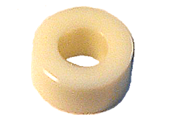 |
| Attach with screws or rivets before soldering. Use two. | |
| The assembly stacks up first the battery case, then the spacer, then the circuit board. The rivet holds everything together. After joining, solder and trim the extra bits. |  |
CONNECTING LEDS TO THE (B)ATTERY POWERED BAUBLE
| The battery powered bauble switches the LEDs at the battery voltage. This means we can drive one LED per channel. The round solder pad is the positive, the square is the negative. |  |
PROGRAMMING YOUR ARDUINO
| To program use the standard 6 pin serial converter. In the Arduino IDE, set the board to ‘Mini 328’ or ‘UNO’ and make sure the com port is selected.
Note – The ground pin is at the top left here, it’s marked ‘GND’. |
 |
| When plugging in the serial dongle, make sure ground inserts the pin with the square around it. If it’s backwards you could damage it. It may be easier to plug it in from the bottom. |  |
| These serial programming adapters can be found on eBay for about $5. It’s most important that it has the FT232RL chip made by FTDI and that it has 6 pins in the order of GND, CTS, 5V, TXD, RXD & DTR. You do not want the CP2102 based adapter. Search for “FT232RL USB To Serial Adapter”. | |
| Your computer may not have the Virtual Serial Port Driver for the serial dongle, it’s here if you need it: http://www.ftdichip.com/Drivers/VCP.htm |
DEMO SKETCHES
| bob_RTTTL_sound_light_0v01 | This sketch plays Nokia ring tone songs. The seven LED channels light up with the seven notes of the scale. |
| Bob_VU_Meter_0v01 | This sketch listens to the microphone and displays the level on the LEDs as a Christmas VU Meter. |
| bob_multi_mode_lights | This sketch was made by Will in the second workshop, it has many modes called by the button. |
| bob_multi_mode_lights_snd | This sketch is the same as above but includes the music player as a mode. This code is preloaded on your MCU. |
Hello I just ordered one of these kits. My 8-year old was looking over my shoulder and just had to have one @grin@. How many of the components come in the kit -it it complete? If not, what is the second IC? -profharris
P.S. would love to attend, but we live in Corpus Christi, Texas. (Deep south Texas @grin@)