DC Servo: In a State of Motion…
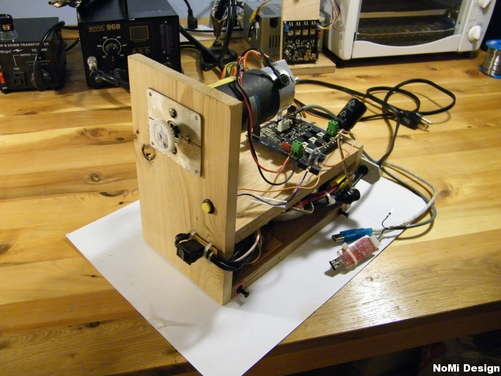
Software and hardware development have converged into a practical test platform. The encoder processing loop has been converted to fast inline assembly and released under GPL. And in the following image, the test platform, consisting of a brushed servo motor, a power supply and a controller was assembled to facilitate rapid software development, research and testing.

The Motor and Power specifications of the test platform are as follows…
| Electrocraft E543 | Power Supply |
|
|
Another view showing the back of the motor, the encoder and the drive. The power supplies and some bulk capacitance are tucked safely inside the box. 
The Controller and Software specifications of the test platform are as follows…
| Controller | Software |
|
|
And finally, that brings us to the tuning software being developed in the Processing environment. Visual tuning method is achieved by introduction of a 200 step disturbance, the resulting action is captured in SRAM with a 1kHz sample rate, passed forward through serial and plotted as position (upper) and velocity (lower).
As can be seen in the following image, the drive first overshoots and then settles out in just under 60 ms. In practical application, the possibility of such disturbance with infinite acceleration is null.

Some refinement of the PIV Algorithm is required to further reduce the settling time. As well as practical experimentation to determine the least number of modifiable coefficients and reduction through coefficient relationships. This is in effort to include the option of on-board tuning potentiometers, thereby greatly reducing setup complexity and setup time.
The software is to be released open source under GPL. The kit will be designed for DIY (some assembly required). The current hardware iteration can be found here: http://krazatchu.ca/wp/2011/11/19/nomi-locus-dc-servo-kit/
UPDATE January 2014
While this project has been on the back burner it is still alive and well. The current version takes form as an Arduino Nano Shield as illustrated below.
I am interested in you progress, I am adding cnc control to a 1926 South Bend 11″ lathe.
This started out as a search for a gearbox and morphed into a control project.
At present I am considering the 08020 drives from CNC4PC…. but I am still assembling parts. I have two servos, a 60 volt 600 watt Electrocraft and a 90 volt (x)watt Marquipt.
Will the drivers you spec’d handle higher power FET’s?
Looks like more choices to make… I’m getting to old for this… LOL
Thanks
paul
WB9HCO
Hi Paul,
That sounds like a fun build, South Bend made some great iron.
The drivers will be capable of meeting your needs when the design wraps up.
As it stands there will be some changes to the flyback dampening for higher power applications.
I will keep you posted as progress continues…
Michael
Hello,
Looking at building a 4th axis and thought this drive might be what i need without breaking the bank.How the progress is going. This looks very promising.
Troy
Hello Troy,
It’s coming together quite well as it’s our primary focus.
We will be releasing a preliminary version for small motors first, the prototype PCBs are currently in production.
Then we will step the power section up and implement some protections including over current, etc.
Michael
I want to connect Moc7811 encoder with atmega 16. I want to know the pin connections. Thanks
The MOC7811 is not an encoder. Google is your friend.
hello mate
how is it going ?
any progress , did you release the schematics and/or PCB files …
is it working ?
Great, Thanks for the Update!
Will the Arduino Nano run normal “C” code with your fast assembler for encoders, etc.?
This is a good idea and should make it much easier for builders. I believe this will be a success in the CNC hobby community. Let us know when kit prices are calculated! I have a good junkbox so a bare board might be good for me.
Thanks
Don
Hi Don,
The Arduino NANO has the same microcontroller, the Atmega328 as the UNO and quite a few other Arduinos.
As such, it will run assembly and C as any other will.
The current software is actually no longer using assembly to poll the inputs, instead it’s using a fast function triggered on hardware interrupt.
There’s a good bit of headroom in processor cycles so it works all as well but is not as cryptic as the assembly.
I will put a spreadsheet together and figure out the price, probably before the end of the week.
Thanks!
Hi krazatchu !
Can you’re upload practical application ? I need it’s
Hi Have been following with much interest. Looks very promising. Are kits for sale yet & please is code open source. Paul
Hi,
Agree with Don 100 %, just what people like me looking for (I’m a machinist , not a coder..).
Presume this is the basis for “underpants”.
Will you be be doing a l298 version, like you have done with previous firmware.
Am very interested in kit / pcb.
Thx
Peter